Honeywell T4 Thermostat Installation Manual: A Comprehensive Plan (Updated 12/05/2025)

Today’s date is 12/05/2025 08:18:10 (). This manual provides detailed instructions for installing and configuring your new Honeywell T4 thermostat, ensuring optimal performance.
Welcome! This section introduces the Honeywell T4 thermostat, a programmable device designed for efficient home climate control. The T4 offers user-friendly operation and advanced features to optimize comfort and energy savings. It’s a smart solution for managing your heating and cooling systems, adapting to your lifestyle and preferences.
This manual will guide you through the entire installation process, from preparing your existing wiring to setting up personalized schedules. Whether you’re a seasoned DIY enthusiast or a first-time installer, these instructions are crafted for clarity and ease of understanding. The T4 supports various system types, including conventional heating and cooling, and heat pumps. Proper installation ensures reliable performance and maximizes the benefits of your new thermostat.
Package Contents & Verification

Before beginning installation, carefully verify the contents of your Honeywell T4 thermostat package. You should find the T4 thermostat unit itself, a mounting backplate, screws and wall anchors for secure attachment, and this comprehensive installation manual.
Additionally, the package includes wire labels to aid in identifying existing wiring, crucial for a smooth transition. Inspect all components for any signs of damage during shipping. If any parts are missing or appear damaged, do not proceed with the installation. Contact Honeywell Support immediately for assistance and replacements. Accurate verification ensures you have everything needed for a successful and trouble-free setup.
Safety Precautions
Prior to installation, always disconnect power to your heating and cooling system at the breaker box to prevent electrical shock. Working with electrical wiring can be dangerous; if you are uncomfortable, consult a qualified HVAC technician.
Ensure the thermostat is installed in a location free from direct sunlight, drafts, and excessive moisture; Do not install near flammable materials. Use only the provided screws and wall anchors to secure the thermostat. Improper installation could create a safety hazard. Always follow local electrical codes and regulations during the installation process. Prioritize safety throughout the entire procedure.
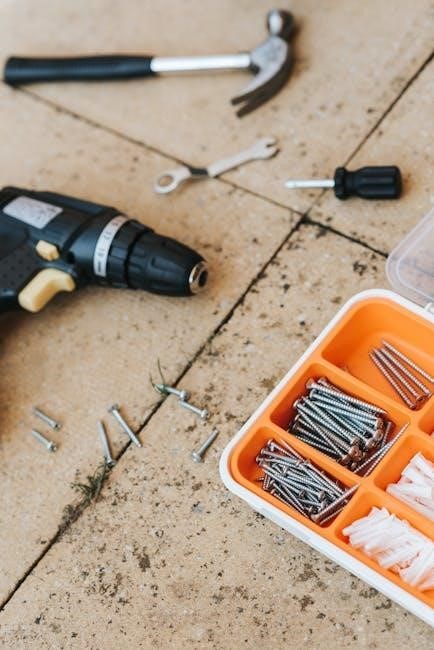
Tools Required for Installation
For a successful Honeywell T4 thermostat installation, you will need a few essential tools. A Phillips head screwdriver is crucial for securing the backplate and thermostat. A small flathead screwdriver may be needed for certain terminal connections. A wire stripper/cutter will help prepare the wires for connection.
Additionally, a level ensures the thermostat is mounted straight. A pencil is useful for marking screw locations. A voltage tester (non-contact) is highly recommended to verify power is off before handling wires. Finally, have a digital camera or smartphone available to document existing wiring before disconnection – this is incredibly helpful!
Understanding the T4 Thermostat Terminals
The Honeywell T4 thermostat utilizes specific terminals for proper heating and cooling system operation. Familiarizing yourself with these is vital; The R terminal provides power, while the C terminal completes the circuit – often required for consistent power. W controls heating, activating your furnace or heat source.
Y activates cooling, engaging your air conditioner. G controls the fan, circulating air throughout your home. Some systems may include additional terminals like Aux (auxiliary heat) or E (emergency heat). Correctly identifying and connecting these wires is paramount for a functional thermostat setup;

Identifying the R, C, W, Y, and G Terminals
The R terminal, typically red, delivers 24V power to the thermostat. The C terminal, often blue, provides a common return path, essential for many modern systems. W, usually white, activates the heating system, signaling the furnace to ignite. Y, typically yellow, energizes the cooling system, starting the air conditioner compressor.
G, generally green, controls the blower fan, circulating air. These color codes aren’t universal; always verify with your system’s wiring diagram. Incorrect connections can damage your HVAC equipment. Carefully label each wire before disconnecting it from the old thermostat to ensure accurate re-installation.
Common Terminal Configurations
Conventional systems frequently utilize R, C, W, and Y terminals for basic heating and cooling. Heat pump systems often incorporate an additional O/B terminal to reverse the valve for heating or cooling. Some older systems may lack a C wire, requiring a C-wire adapter for proper T4 functionality.
Millivolt systems, common in fireplaces, use different wiring and aren’t compatible with standard T4 installation. Always consult your HVAC system’s documentation to identify the correct terminal configuration. Incorrect wiring can lead to system malfunction or damage. Documenting the existing setup before disconnecting wires is crucial for a smooth transition.
Preparing for Installation: Powering Down
Safety is paramount! Before commencing any wiring, completely disconnect power to your HVAC system at the breaker box. Locate the breaker controlling your furnace and air conditioner, and switch it to the “OFF” position. Double-check with a non-contact voltage tester to confirm power is indeed off at the thermostat wires.
Failure to do so poses a serious risk of electrical shock and potential damage to your equipment. This step is non-negotiable. Once power is confirmed off, proceed with labeling the existing wires – a crucial step for correct re-installation.
Removing Your Old Thermostat
Carefully remove the cover of your existing thermostat, often by gently prying it off or releasing a latch. Before disconnecting any wires, take clear, high-resolution photos of the wiring configuration. This visual record is invaluable during the installation process.
Next, carefully label each wire with the corresponding terminal designation – R, C, W, Y, and G – using the provided wire labels. Securely attach the labels to each wire. Once labeled, disconnect the wires one at a time, avoiding any accidental shorts.
Labeling Existing Wires
Accurate wire labeling is crucial for a successful Honeywell T4 installation. Use the provided wire labels – these are specifically designed to adhere securely and remain legible. Match each wire to its corresponding terminal on the old thermostat. Common designations include R (power), C (common), W (heating), Y (cooling), and G (fan).
Wrap each label tightly around the insulated wire, ensuring the text is clearly visible. Double-check your labeling against the photo you took earlier. Incorrect labeling can lead to system malfunctions. If wires are unclear or damaged, consult a qualified HVAC technician before proceeding.
Disconnecting the Old Thermostat
Before disconnecting any wires, absolutely ensure the power to your HVAC system is completely shut off at the breaker box. This prevents electrical shock and potential damage. Gently loosen the screws holding the old thermostat’s wires in place. Carefully pull each wire straight out, avoiding any bending or twisting.
As you disconnect each wire, refer to your labels to confirm its function. Do not allow the wires to fall back into the wall! Once all wires are disconnected, carefully remove the old thermostat baseplate from the wall.
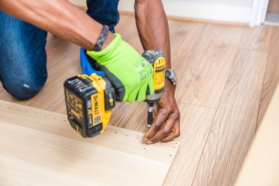
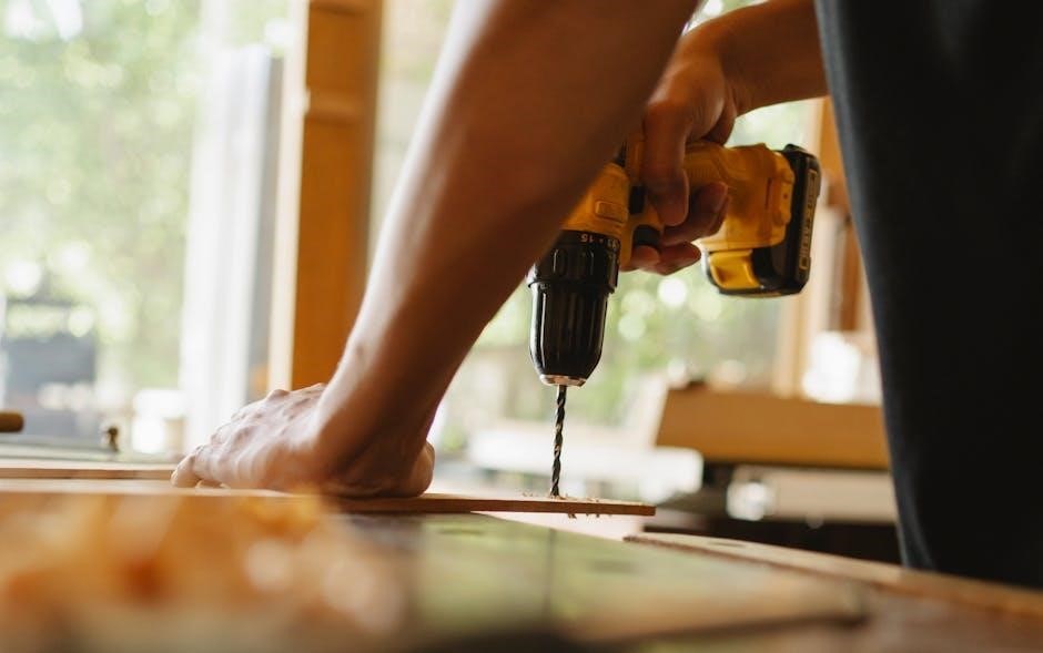
Installing the T4 Thermostat Backplate
Begin by positioning the T4 thermostat backplate on the wall where your old thermostat was located. Ensure it’s level using a small bubble level for accurate installation. Mark the screw holes with a pencil. If necessary, use the provided wall anchors for secure mounting, especially on drywall.
Carefully drill pilot holes at the marked locations. Attach the backplate to the wall using the screws provided, tightening them firmly but not excessively. Double-check that the backplate is securely fastened and level before proceeding to the wiring stage. A stable backplate is crucial for proper thermostat function.
Connecting the Wires to the T4 Thermostat
Carefully match each labeled wire from your wall to the corresponding terminal on the T4 thermostat backplate. Gently insert each wire fully into its designated terminal, ensuring a secure connection. Avoid forcing the wires, as this could damage the terminals.
Double-check all connections against your wiring diagram and the terminal identifications (R, C, W, Y, G). A loose or incorrect connection can cause system malfunctions. Once all wires are connected, gently tug on each wire to confirm it’s firmly held in place. Proceed cautiously to avoid electrical shock.
Wiring for Heating Systems
For standard heating systems, connect the ‘W’ wire to the ‘W’ terminal on the T4 thermostat. This wire signals the furnace to turn on for heat. The ‘R’ wire provides 24V power, connecting to the ‘R’ terminal. A ‘C’ wire (common wire) is often required for consistent power; connect it to the ‘C’ terminal if present.
If you have a heat pump, wiring may differ – consult the ‘Wiring for Heat Pump Systems’ section. Ensure the furnace power is OFF during wiring. Incorrect wiring can damage your heating system. Verify all connections before restoring power.
Wiring for Cooling Systems
To connect your cooling system, locate the ‘Y’ wire and connect it to the ‘Y’ terminal on the Honeywell T4 thermostat. This wire activates the compressor for cooling. The ‘R’ wire, providing 24V power, connects to the ‘R’ terminal. A ‘C’ wire (common wire) is highly recommended for reliable operation; connect it to the ‘C’ terminal if available.
Always ensure power is OFF before making any wiring connections. Double-check all connections for security before restoring power to prevent damage. If you have a heat pump, refer to the dedicated ‘Heat Pump Systems’ wiring instructions.
Wiring for Heat Pump Systems
Heat pump wiring differs significantly. Connect the ‘Y’ wire to the ‘Y’ terminal for cooling, but also identify the ‘O/B’ wire; This wire reverses the valve for heating; its terminal depends on your system’s configuration – ‘O’ for cooling initiation, ‘B’ for heating. The ‘R’ wire provides power to the ‘R’ terminal, and a ‘C’ wire is crucial for stable operation, connecting to the ‘C’ terminal.
Verify your heat pump type before connecting the ‘O/B’ wire. Incorrect wiring can cause reversed heating/cooling. Always power down before wiring and double-check connections.
Attaching the T4 Thermostat to the Backplate
Carefully align the Honeywell T4 thermostat with the mounted backplate. Ensure all wires are neatly tucked inside the wall opening, preventing any pinching or strain. Gently press the thermostat onto the backplate until it clicks securely into place; A firm, even pressure is key to a solid connection.
Verify the thermostat is flush against the wall and doesn’t wobble. If it doesn’t seat properly, re-check wire connections and alignment. Avoid forcing it, as this could damage the unit or wiring. A secure attachment is vital for proper operation and aesthetics.
Powering On and Initial Setup
Restore power to your HVAC system at the breaker box; The Honeywell T4 thermostat should power on automatically, displaying the welcome screen. If it doesn’t, double-check the breaker and wiring connections. The initial setup will guide you through essential configurations.
Follow the on-screen prompts to set your preferred language, date, and time. The thermostat may automatically detect your system type, but verify this information for accurate operation. Confirm the system type (heating, cooling, or heat pump) and proceed to the next step.
Programming the Basic Settings
Access the settings menu on your Honeywell T4 thermostat to personalize your comfort preferences. Begin by setting the date and time accurately; this is crucial for scheduling functions. Next, configure temperature units – choose between Fahrenheit (°F) or Celsius (°C) based on your preference.
Explore options for display brightness and backlight duration to optimize visibility. Consider enabling or disabling features like auto-changeover (switching between heating and cooling) based on your system’s capabilities. These basic settings lay the foundation for a customized and efficient heating and cooling experience.
Setting the Date and Time
Navigate to the “Date/Time” menu within the thermostat’s settings. Use the up and down arrow buttons to adjust the month, day, and year. Confirm each selection by pressing the “Select” or “OK” button. Repeat this process for setting the hour and minute, ensuring you correctly indicate AM or PM.
Accurate date and time settings are vital for the proper functioning of scheduling features. Incorrect settings will lead to inaccurate program execution. Double-check your entries before saving to guarantee your Honeywell T4 thermostat operates as intended, providing consistent and reliable climate control.
Configuring Temperature Units (°F or °C)
To change the temperature display, access the “Preferences” or “Settings” menu on your Honeywell T4 thermostat. Locate the option labeled “Temperature Units” or similar. Use the arrow buttons to toggle between Fahrenheit (°F) and Celsius (°C). Confirm your selection by pressing the “Select” or “OK” button.
This setting affects all temperature displays on the thermostat and within the mobile app, if connected. Choosing the correct unit ensures accurate readings and comfortable climate control. Verify your preference immediately after installation for consistent temperature monitoring and scheduling.
Creating a Heating/Cooling Schedule
Access the “Schedule” menu on your Honeywell T4 thermostat to program customized heating and cooling periods. You can typically define different settings for weekdays and weekends, or create a unique schedule for each day. Set specific start and stop times for heating and cooling, along with desired temperatures for each period.
Utilize the thermostat’s interface to add, edit, or delete schedule events. Consider your daily routines and preferences to optimize energy savings and comfort. A well-planned schedule minimizes energy waste while maintaining a pleasant indoor environment.
Understanding the T4 Thermostat Display Icons
The Honeywell T4 thermostat utilizes various display icons to communicate its status and operation. A flame icon indicates the heating system is active, while a snowflake icon signifies cooling. A fan icon shows the fan is running, and its status (auto or on) is also displayed.
Other icons may represent system modes like ‘Hold’, ‘Sleep’, or ‘Away’. A battery icon alerts you to low battery levels. Familiarizing yourself with these icons allows for quick assessment of your system’s performance and troubleshooting potential issues. Refer to the full manual for a complete icon glossary.
Using the Fan Control Settings
The Honeywell T4 thermostat offers flexible fan control settings to optimize comfort and air circulation. You can select ‘Auto’ mode, where the fan operates only during heating or cooling cycles. Alternatively, choose ‘On’ mode for continuous fan operation, improving air mixing and potentially enhancing comfort.
Some models feature a ‘Circulate’ setting, periodically running the fan to maintain consistent temperatures. Adjusting these settings impacts energy consumption and indoor air quality. Experiment to find the optimal configuration for your home and preferences. Consult the full manual for detailed instructions on accessing and modifying these settings.
Troubleshooting Common Installation Issues
Installation can sometimes present challenges. If the thermostat isn’t powering on, double-check the C-wire connection and breaker. Incorrect temperature readings often stem from improper thermostat placement – avoid direct sunlight or drafts. Verify wiring connections against the diagram; a loose wire can cause erratic behavior.
If the system doesn’t respond to commands, ensure compatibility with your HVAC system. A faulty wire or incorrect configuration can also be the culprit. Refer to the detailed troubleshooting section in the manual or contact Honeywell support for assistance. Always prioritize safety when diagnosing issues.
Thermostat Not Powering On
If your Honeywell T4 fails to power on, begin by verifying the breaker supplying power to your HVAC system is switched on. Crucially, check the C-wire connection – a missing or improperly connected common wire is a frequent cause. Ensure the wire is securely fastened to the ‘C’ terminal on both the thermostat and the furnace control board.
Inspect the batteries (if applicable) and replace them with fresh ones. A loose connection anywhere in the wiring can also prevent power-up. Double-check all wire connections at both the thermostat and the furnace. If problems persist, consult a qualified HVAC technician.
Incorrect Temperature Readings
If the Honeywell T4 displays inaccurate temperatures, first ensure the thermostat isn’t directly exposed to sunlight, drafts, or heat-generating appliances. These external factors can significantly skew readings. Verify proper thermostat placement – it should be on an interior wall, away from obstructions.
Calibrate the temperature within the thermostat’s settings menu; a slight offset adjustment may be necessary. Confirm that the thermostat is correctly sensing the room temperature and isn’t influenced by nearby heat sources. If the issue continues, a faulty temperature sensor might require professional assessment and replacement.
Resetting the Honeywell T4 Thermostat
To reset your Honeywell T4 thermostat, navigate to the settings menu on the device. Locate the “Reset” or “Factory Defaults” option – its exact location may vary slightly depending on the firmware version. Confirm your decision as resetting will erase all personalized settings, including schedules and Wi-Fi connections.
A complete reset restores the thermostat to its original factory state, useful for troubleshooting persistent issues or preparing the device for a new user. After resetting, you’ll need to reconfigure all settings, including date, time, temperature preferences, and any programmed schedules.
Wi-Fi Connectivity and Mobile App Setup (If Applicable)
For models with Wi-Fi capability, download the Honeywell Home app from your device’s app store. Create an account or log in if you already have one. Follow the in-app instructions to add your T4 thermostat to your network. Ensure your thermostat is in pairing mode – typically activated through the settings menu on the device itself.
Once connected, the app allows remote control, scheduling adjustments, and access to energy usage reports. You can also integrate the thermostat with other smart home platforms. A stable Wi-Fi connection is crucial for optimal performance.
Battery Replacement
Your Honeywell T4 thermostat may utilize batteries as a primary or backup power source. Low battery indicators will appear on the display, prompting replacement. Use only fresh, alkaline batteries of the correct size – typically AA. Locate the battery compartment, usually on the side or back of the thermostat, and open it carefully.
Remove the old batteries and insert the new ones, ensuring correct polarity (+ and -). Close the battery compartment securely. The thermostat may briefly power off during battery replacement, but will automatically restart. Regularly check battery levels to avoid interruptions.
Advanced Features and Settings
The Honeywell T4 thermostat offers several advanced features beyond basic heating and cooling control. Explore options like Smart Recovery, which learns your heating/cooling patterns for optimized efficiency. Geofencing utilizes your smartphone’s location to adjust temperatures automatically when you’re away. Customize Filter Change Reminders to maintain air quality.
Access these settings through the thermostat’s menu system or, if connected, via the Honeywell Home mobile app. Experiment with different settings to personalize your comfort and energy savings. Detailed explanations of each feature are available within the app and on Honeywell’s support website.
Warranty Information
Your Honeywell T4 thermostat is covered by a limited warranty against defects in materials and workmanship. This warranty typically lasts for a period of one (1) year from the date of original purchase. The warranty covers repair or replacement of the defective product, at Honeywell’s discretion.
This warranty does not cover damage resulting from improper installation, misuse, abuse, or unauthorized modifications. Proof of purchase is required for all warranty claims. For complete warranty details, including limitations and exclusions, please visit Honeywell’s website or contact Honeywell Customer Support.
Contacting Honeywell Support
For assistance with your Honeywell T4 thermostat, several support options are available. You can visit the official Honeywell Home website for a comprehensive FAQ section, troubleshooting guides, and downloadable resources. Alternatively, you can reach Honeywell Customer Support directly via phone. The support number is prominently displayed on the Honeywell Home website and in the product documentation.
Live chat support may also be available during business hours. When contacting support, please have your thermostat model number and date of purchase readily available. Honeywell aims to provide prompt and helpful assistance to ensure your complete satisfaction with your new thermostat.
Frequently Asked Questions (FAQ)
Q: My T4 thermostat isn’t powering on. What should I do? A: First, verify the C-wire connection is secure. If absent, a C-wire adapter may be needed. Q: Can I control my thermostat remotely? A: Yes, if you have a compatible model with Wi-Fi connectivity, using the Honeywell Home app.
Q: How do I reset the thermostat to factory settings? A: Consult the “Resetting the Honeywell T4 Thermostat” section for detailed instructions. Q: Is professional installation required? A: While not always necessary, it’s recommended if you’re uncomfortable with electrical wiring. Q: What if my system isn’t compatible? A: Contact Honeywell Support for assistance.